IJN Carrier Wreckage- Identification Analysis
Executive Brief
This analysis was undertaken to help ascertain the point of origin of a piece of wreckage recently discovered by Nauticos. It is believed that this artifact originated from a Japanese aircraft carrier sunk at the Battle of Midway. In order to help identify the artifact’s origin, a thorough examination of each of the three carriers believed sunk in the general vicinity of the wreckage find—the Akagi, Kaga, and Sôryû—was undertaken to correlate the undersea photographic evidence with known characteristics of these three warships. Extensive usage was made of both English-language and Japanese sources in support of this effort.
The results of the analysis demonstrate conclusively that the wreckage originated from the Japanese aircraft carrier Kaga. Specifically, it is composed of two 25mm anti-aircraft gun tubs, and their associated gallery structures, that were located on the forward end of the starboard aft (starboard quarter) machine gun gallery of the vessel.
The second portion of the analysis, which deals with the circumstances surrounding how and when the wreckage was created, is less conclusive. The gaps in the historic record concerning Kaga’s demise are large, and it is impossible to pinpoint the exact time when the wreckage may have broken off from the ship. Nevertheless, we believe that the event probably occurred sometime between U.S.S. Nautilus’ attack on the ship (at 1400), and her abandonment at 1640.
Introduction
Recently, Nauticos has discovered a significant piece of wreckage on the ocean floor off of the island of Midway. From all appearances, the artifact originates from one of the four Japanese carriers sunk at the Battle of Midway in June 1942. This is a tremendously important find to the historic record. Nauticos intends a follow-on expedition to the Midway battlefield shortly. At such time they hope to locate the ship from which the wreckage came. In support of this expedition, it is important to positively identify the wreckage found thus far.
Analysis Goal
The goal of this analysis is to positively identify the ship from which the wreckage came. On the basis of the photographic evidence to hand, we believe that this analysis conclusively achieves this primary goal.
Secondarily, the analysis seeks to lay out a theory regarding how and when the artifact was created, and how it ended up on the seabed in its present state. In support of this objective, we believe that general comments can be made as to its origins, but gaps in the historic record prevent us from conclusively determining the exact timing and circumstances surrounding the creation of the wreckage.
Analytical Approach
This analysis builds on the work performed in our earlier Preliminary Analysis document, dated December 6, 1999. However, in contrast to the earlier document (which compared a textual description of the wreckage against every available gun tub aboard the three ships), this analysis is more descriptive in nature. We seek to recreate the thought processes and arguments that led to the final identification of the wreckage.
We rely primarily on the photographic evidence made available from Nauticos, as well as photos, line art, and models of Japanese warships. As in the first document, only three of the Japanese carriers that were sunk at the Battle of Midway are included in this analysis. These are the Akagi, Kaga, and Sôryû. The fourth Japanese carrier lost, the Hiryû, is excluded from examination due to the distance she likely sank (approximately 50 miles northwest, i.e. downwind) from the location where the wreckage was discovered.
Platform Nomenclature
Throughout this analysis, the gun tub numbering scheme put forth in the Preliminary Analysis document is used. In this system, gun tubs are referred to by: Shipname-Side (port, starboard, or bow)-Mount#. Thus, “Kaga-P#4” refers to the fourth mount back from the bow on the port side of Kaga.
Japanese Carrier Equipment
This analysis centers on the identification of a piece of wreckage belonging to a Japanese aircraft carrier. Most of the identifiable items in this area of IJN carriers are centered on anti-aircraft armament and flight deck operations. This section provides additional details regarding the types of equipment to be found on or near the edges of Japanese flight decks and in the AA galleries adjacent to them.
Heavy Anti-Aircraft Armament
These weapons were used to engage enemy aircraft at longer ranges. Japanese fleet carriers typically carried between 12 and 16 such weapons, universally in twin mounts. Such mounts were usually sponsoned out from the side of the ship, with a heavy tapering cylindrical support structure beneath the mount. Typically, such mounts were incompletely shielded, and usually only carried light sheet metal across their fronts to protect the crew from splinters. However, both heavy and light AA weapons, and their associated fire-control equipment, were fully enclosed when mounted on the starboard quarter of the ship, in order to protect the crew from boiler gases emanating from the downswept funnel. This feature is true for each of the four Japanese carriers lost at the Battle of Midway, except for Akagi, where the rearmost starboard 25mm mounts were left unshielded.
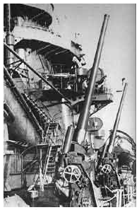
Figure 1: Single barreled 120mm AA mount aboard a heavy cruiser. (Scanned from John Campbell’s Naval Weapons of World War Two)
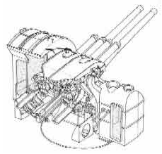
Figure 2: Standard dual 127mm AA mount. (Scanned from Janusz Skulski’s Heavy Cruiser Takao) By the time of the Pacific War, the newer 127mm/40 had largely superseded the 1920s vintage 120mm/45 mount in most of the Imperial Navy’s warships. Akagi, however, still retained the older weapon, despite her 1938 refit.
Light Anti-Aircraft Armament
The standard Japanese light anti-aircraft gun was a 25mm weapon, originally developed by the French firm Hotchkiss and produced by the Japanese beginning in 1936. It came in single, dual, and triple-barreled configurations. At the time of the Battle of Midway, the dual mount was still the most common among IJN carriers, although Hiryû (the newest of the Japanese carriers at Midway) carried several triple mounts at the time of her loss.
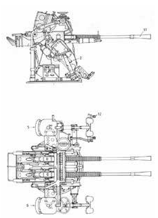
Figure 3: Dual 25mm AA mount. (Scanned from Janusz Skulski’s Heavy Cruiser Takao)
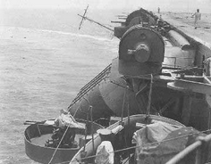
Figure 4: Twin 25mm mount aboard Kaga. This is mount S#5. The large director above the funnel is a Type 91 system for the starboard 8” battery. (Scanned from Maru Special)
Fire Control Systems
The standard Japanese heavy AA (i.e. for 120mm and 127mm weapons) fire-control system was the Type 94 Koshaki, first adopted in 1934. It was used by practically every Japanese warship for AA control. Typically, two Type 94 directors were carried aboard each carrier—one apiece for the port and starboard heavy AA batteries.
Light AA weapons were controlled by the Type 95 system introduced in 1935. This system was typically located somewhere close by the guns it controlled, as a pointer would have to manually point out targets to the guns being directed. (Remote power control of 25mm mounts was apparently only available in the triple barreled version, and seemingly towards the end of the war. It is not known whether Hiryû was so fitted at the time of her loss.)
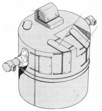
Figure 5: Type 94 heavy AA director. (Scanned from Hasegawa’s Nihon no Kokubokan)
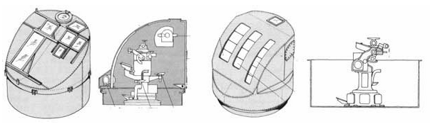
Figure 6: Type 95 directors, in both shielded and unshielded versions. (Scanned from Tamiya’s Random Japanese Warship Details, Volume 2.)
Radio Aerial Platforms
In addition to gun and fire-control platforms, most Japanese carriers mounted at least four radio aerials abreast their flight decks. These aerials were raised into a vertical position during time in port, but could be lowered to a horizontal position during flight operations.

Figure 7: Typical radio aerial platform, with aerial in the raised position. (Scanned from Hasegawa’s Nihon no Kokubokan)
Landing Light Arrays
Japanese aircraft carriers carried landing aides to help pilots determine whether or not their landing approach was correct in terms of both descent angle and angle relative to the centerline of the flight deck. The equipment used was a set of colored lights (red and green) which were aimed at different angles upwards and over the stern of the ship. The lights themselves were carried atop a hinged supporting arm. Often, the arm was affixed to the antiaircraft machine gun galleries, either to the gallery structure or an actual gun tub. However, landing light arrays could also be attached to other platforms on the side of the ship.
When the lights were in use, the arm was folded outward perpendicular to the flight deck. The arm and lights could be folded flat against the side of the ship when not in use.
Each carrier typically carried several sets of lights (4 sets being a common number). The positioning of the lights themselves was distinct to each carrier. From the available sources, we know the position of Akagi’s landing light arrays very precisely, Kaga’s less so, and Sôryû’s hardly at all. The following pictures help illustrate how such arrays were carried and used aboard ship.
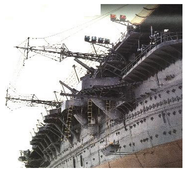
Figure 8 : Picture of 1:100 scale model of Zuikaku, showing landing light arrays, radio aerials, netting, and port quarter anti-aircraft platforms. (Scanned from Gakken Pacific War Series, Volume #13.)
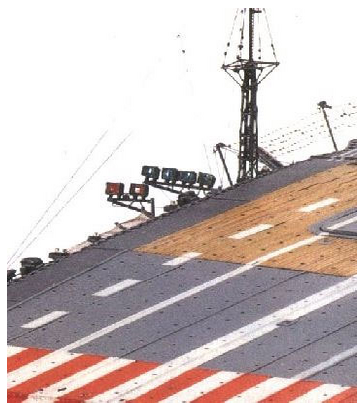
Figure 9: Another shot of Zuikaku, showing the landing light array from above. (Scanned from Gakken Pacific War Series, Volume #13.)
Nets
Japanese aircraft carriers (like those of most other nations) carried steel cable nets along the sides of their flight decks which could help prevent heavy objects (planes, personnel, ordnance, etc.) from rolling off the edge of the flight deck and damaging themselves and/or the galleries beneath. Such nets were suspended from heavy steel arms along the sides of the flight deck.
Sources Used
Brown, David. Aircraft Carriers. New York: Arco Publishing, 1977.
Campbell, John. Naval Weapons of World War Two. London: Conway Maritime Press Ltd., 1985.
Chesneau, Roger. Aircraft Carriers of the World, 1914 to the Present: An Illustrated Encyclopedia. London: Arms and Armour Press, 1984.
Drawings of Imperial Japanese Naval Vessels—Aircraft Carrier, Seaplane Carrier, Submarine. Model Art, Volume #3. Japan.
Gakken Pacific War Series, Vol. #13 (Shôkaku and Zuikaku) and Vol. #14 (Akagi, Kaga, and Hiryu). Japan.
Jentschura, Hansgeorg; Dieter Jung; and Peter Mickel. Warships of the Imperial Japanese Navy, 1869-1945. Annapolis, Md.: Naval Institute Press, 1977.
Maru Special, Issue #1 (Akagi and Kaga). Japan.
Nihon no Kokubokan (Japanese Aircraft Carriers). Hasegawa / Gran Prix Shuppan.
Random Details of Japanese Warships, Volumes I and II. Tamiya Model Co.
Ships of the World. Japan.
Skwiot, M., A. Jarski. Akagi. Gdansk: A.J. Press, 1994.
Watts, Anthony, Gordon Watts. The Imperial Japanese Navy. New York: Doubleday and Co., 1971.
Yuki, Takeshi. Watercolor Paintings of Imperial Japanese Navy Ships. Tokyo: Kaijinsha Co. Ltd, 1990.
Comments on Sources
In general, Jentschura and the Hasegawa carrier book were the most useful sources from a direct visual standpoint, although the A.J. Press book on Akagi is clearly the best set of plans available on any of the three ships in question. It contains a very detailed 1:400 foldout plan and side elevations of the ship after her 1938 reconstruction which provided a wealth of detailed identification information. David Brown’s book is light on actual drawings but contains extremely useful technical tidbits concerning hanger decks heights, loading characteristics and so on. Roger Chesneau’s book is also useful in this respect, but the drawings are uniformly crude and poorly executed.
David Dickson supplied additional published and unpublished carrier plans from various sources. These have been forwarded to Nauticos, and include internal plans of both Kaga and Akagi. The Kaga plans are crude, but do show general internal arrangements, which may prove useful at a later point in time.
1:700 plastic models of both Kaga and Akagi were used to fill in certain conceptual details, particularly in the aft AA gallery areas. The 1:700 kit of Sôryû from the Aoshima Model Co. was deliberately not used, as Aoshima is well known in the plastic modeling community for producing under-detailed and indeed downright inaccurate models. The Tamiya Model Co. Random Details of Japanese Warships supplied many interesting and useful visual details on weapons, fire-control systems, and hull structure.
John Campbell’s Naval Weapons of World War Two is the standard English-language text on naval weapons of all kinds, and also includes useful details on fire-control systems, ammunition, radar, and related details.
Since the time of the December Analysis, the authors have also begun to use two books in the Gakken Pacific War series. These volumes not only contain useful photographic material and line drawings, but also include color photographs of large-scale (1:100 and 1:200) models of Japanese carriers. The models contained a wealth of useful details which help develop spatial context around the wreckage photographs.
Analysis Part One: Ship Identification
Description of Wreckage
An annotated photomosaic of the wreckage is shown below. The wreckage is a portion of a ship’s bulkhead, to which are attached two round platforms of similar size. The piece has ended up in an inverted position on the seabed floor, so that the viewer is looking at the underside of the structures themselves (almost as if one were standing at the edge of the ship outside the lower hanger deck and looking up at the gun galleries from beneath). The artifact has been severely distorted, the piece having been bent near the center of the bulkhead and rotated around its vertical axis by about 75 degrees, thus forming a concave shape that is more pronounced the further down towards the platforms one goes. This has resulted in the two main platforms (which are 25mm gun tubs) partially facing each other, when on the original ship they would have been side by side and separated by some 10 feet. Points of interest include:
1. 25mm gun tub.
2. 25mm gun tub.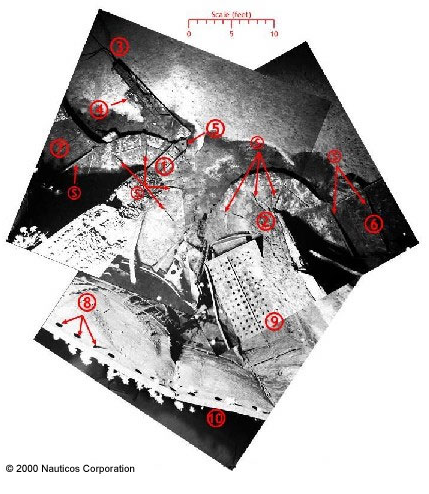
3. Landing light array.
4. Landing light.
5. Hinge structure for landing light arm.
6. Gallery structure with support structures.
7. Gallery structure with support structures.
8. Rivet holes in lower edge of bulkhead (the size of the rivet holes is distorted due to their proximity to the camera).
9. Observation platform (?) with perforated drain holes.
10. Lower edge of bulkhead. Note the apparently very clean line of separation. Support structures on the underside of the tubs and galleries are indicated with an “S”.
A second mosaic partially shows the “backside” of the artifact, which would at one time have been on the interior of the ship.
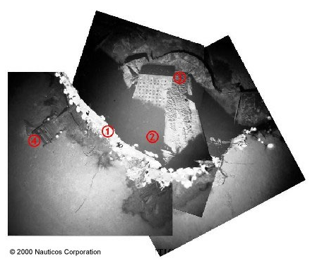
1. Lower edge of bulkhead. Objects towards the upper right are “outside” the ship; objects to the lower left are “inside” the hanger deck.
2. Observation platform (?).
3. 25mm antiaircraft gun tub.
4. Stairway.
These two mosaics comprise the primary photographic evidence that will be used throughout the remainder of the analysis to identify the ship.
Basic Nature of the Wreckage
The first question a dispassionate observer might ask upon seeing photographs of the wreckage is, “How do you know that this artifact is from a Japanese warship?” Put simply, WWII-era Japanese naval architecture had a style, and the wreckage clearly evokes that style. The usage of radial support buttresses around a central inclined column to support the platforms, the riveted hull structure, the weight-saving perforations found in what looks to be an observation platform beneath the tubs, the characteristic shape of the landing light array; all are sound primary evidence that this artifact did not originate from an fishing boat, or a contemporary oil tanker. As a result, we felt confident in proceeding to an identification of the ship itself.
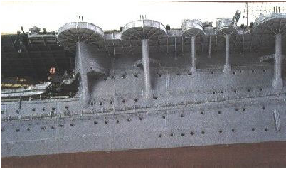
Figure 10: Upward-looking shot of 1:100 model of Zuikaku, showing typical Japanese aircraft carrier gun platform support structures. (Scanned from Gakken Pacific War Series, Volume #13.)
Japanese Carriers
The Akagi
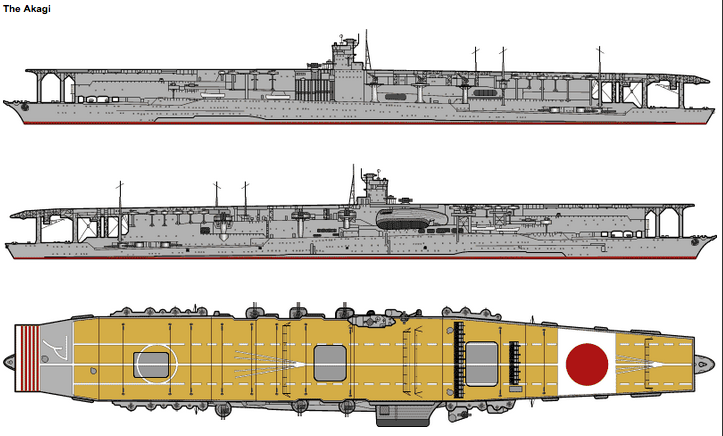
Figure 12: The Akagi in 1942. (Scanned from Jentschura et. al. Warships of the Imperial Japanese Navy, 1869-1945)
Surprisingly, the very nature of the landing light array dismisses Akagi outright. Akagi and Hiryû are the best-documented of the carriers at Midway, and we have very good 1:400-scale plans of Akagi taken from a Polish work on the ship. These plans clearly show that Akagi had four landing light arrays—two forward, and two aft.
The forward arrays were attached to platforms fairly far forward on the flight deck, which were not part of any 25mm gallery structure. And while the aft arrays were mounted aboard the 25mm galleries, they were affixed to the gallery wall itself, rather than the apex of a 25mm gun tub. Thus, according to the best plans we have available, Akagi can be eliminated from consideration.
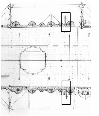
Figure 13: Akagi’s aft landing lights. (Scanned from 1:400 scale planes in AJ Press Akagi)
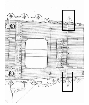
Figure 14: Akagi’s forward landing lights. (Scanned from 1:400 scale planes in AJ Press Akagi)
The Sôryû
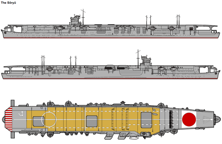
Figure 15: Sôryû in 1942. Note the very complex nature of the ship’s port side bulkheads, with numerous ventilation trunks. (Scanned from Jentschura et. al. Warships of the Imperial Japanese Navy, 1869-1945)
The case surrounding the Sôryû is more complex. The photographic record of Sôryû is limited, and the available plans of her are much less detailed than those of Akagi. For instance, it was not possible to determine where she carried her landing light arrays from either the photographic record or the line drawings available. However, a strong case can be made on the basis of other evidence.
Sôryû was a much smaller ship than either Akagi or Kaga. While the latter were built on top of capital ship hulls (a battlecruiser and battleship, respecitively), the Sôryû and her slightly larger sister Hiryû were based on heavy cruiser hulls and machinery sets. Yet they mounted an airwing and anti-aircraft armament that were similar in scale to the larger fleet carriers. As a result, these were very tight, cramped designs, and this is reflected in the layout of their anti-aircraft armament and fire-control facilities. Sôryû‘s 25mm galleries are smaller, contain fewer gun mounts, and are more cramped. Type 95 directors are often mounted practically adjacent to the mounts they control.
As a result, it is difficult to find any galleries aboard Sôryû that match the six requirements set out previously. The only likely candidates are the P#2-P#4 and P#5-P#7 galleries on the port side of the vessel. Each contains three 25mm mounts. However, the P#2-P#4 gallery can be dismissed because of the complex hull structure directly beneath the gallery (please refer to the portside view of Sôryû in Figure 15 above). The bulkhead is clearly not flat in this area, and there are no portholes in evidence.
Similarly, the bulkhead underneath P#5-P#7 is largely occupied by boiler room ventilator intakes. Not withstanding that the wreckage is partially crushed in the center, we find it unlikely that we would have missed seeing a structure as prominent as a ventilator trunk in this vicinity. And no portholes would be visible in such a structure.
In addition, there is a Type 95 director directly between P#5 and P#6, and another platform directly abaft P#7, meaning that the gallery structure does not match the rather expansive gallery seen in the wreckage, which continues 7-8 feet in both fore and aft directions without encountering any other platforms.Lastly, even though we have no direct evidence of light array placement aboard Sôryû, we feel that it is less likely that these arrays would be mounted in the vicinity of the two portside 25mm galleries. Landing light arrays tended to be located near the quarters of the ship, whereas these two galleries are fairly amidships.
The resulting picture is of a ship whose primary physical features cannot match the wreckage as seen on the bottom, for a host of circumstantial reasons. Even without direct evidence as to the placement of the landing light arrays, we feel confident in dismissing Sôryû from contention.
The Kaga
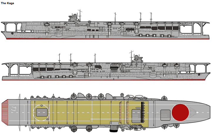
Figure 16: Kaga in 1942. (Scanned from Jentschura et. al. Warships of the Imperial Japanese Navy, 1869-1945)
By process of elimination, we are left with the Kaga. And as it turns out, there is important photographic evidence that comes out strongly in support of Kaga’s case. Kaga’s starboard bow 25mm battery (S#3, S#4, and S#5) can be eliminated because the mounts located here do not form a gallery, being individually sponsoned out from the ship (this is shown nicely in Figure 4, presented in the earlier “Japanese Carrier Equipment” section.) This leaves the aft galleries.
Most of the gun tubs in the aft galleries are problematic. Like Sôryû, Kaga also Type 95 directors located very near some of her 25mm tubs. Drawings differ as to how close, with some drawings (notably the illustration of Kaga in Gakken #14) showing the guns and directors in separate tubs, albeit jammed right next to each other. Another source, Hasegawa’s Nihon no Kokubokan, suggests that the two tubs were actually merged to form a hybrid tub. This tub has an unusual shape, with a bulge towards the forward part of the tub that housed the Type 95 equipment (illustrated in Figure 17). This hybrid tub arrangement seems to be supported, at least for Kaga’s port gallery, by close examination of the photograph in Figure 18, although it is difficult to tell for certain.
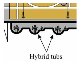
Figure 17: Hybrid gun/fire-control director tub aboard Kaga.
Yet the wreckage photographs seem to support the idea that both of the gun tubs on the bottom were fully semi-circular in nature. This indicates that they could not have been “hybrid” 25mm/Type 95 tubs. That, in turn, requires that we locate two “pure” semi-circular 25mm tubs that are adjacent to each other, and which have a gallery structure extending both fore and aft of their position.
This new requirement rules out Kaga’s port gallery. On that gallery, “hybrid” gun tubs occupy the two middle positions of the four, meaning there are not two adjacent “pure” tubs to be had. This leaves the starboard aft gallery as the only structure aboard Kaga that has a chance to satisfy the requirements. We are, so to speak, down to our last nickel.
Fortuitously, the two forward tubs (S#8 and S#9) in the starboard gallery, according to every source we have at hand, are purely semicircular in nature. Furthermore, the gallery structure in this area runs both forward (towards the 127mm battery) and aft (towards mounts S#10, S#11, and S#12). There is a nice separation between tubs in the area. The question then becomes, does either of the two forward tubs contain a landing light array that will match the wreckage?
The photographic record of Kaga is nearly as weak as Sôryû’s. However, there is a surprisingly good overhead shot of Kaga available (Figure 18) which shows her flight deck in some detail.
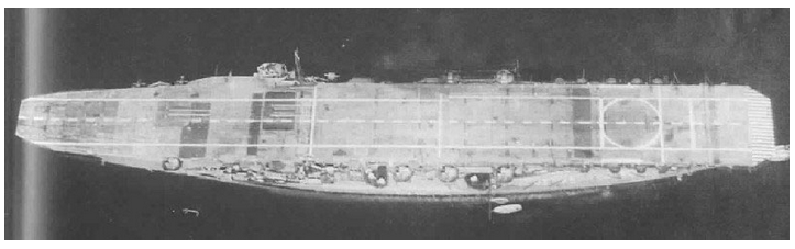
Figure 18: Kaga, photographed in April 1941, showing her flight deck and anti-aircraft galleries. (Scanned from Maru Special)
A close examination of this photograph reveals that Kaga did indeed carry a light array on the second tub in the starboard gallery, on mount S#9. The landing light array can be made out as a thicker line in the magnified photograph at right. The array can be seen to project further outboard than the net supports that line the flight deck in the area. More important, it is clearly mounted in the center of the gun tub structure, and not immediately abaft it (as was the case with Akagi’s aft galleries).
This in itself is strong primary evidence in favor of mount S#9 carrying a gun tub. It is further reinforced by an illustration recently published in the Gakken Pacific War Series Volume #13, which illustrates Kaga’s starboard side quite clearly (see Figure 20). In this drawing, mount S#9 is shown having a landing light array attached to it.
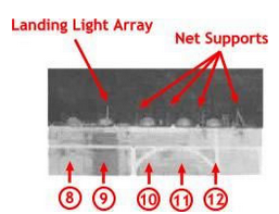
Figure 19: Magnification of Kaga’s starboard aft 25mm gallery. Mount numbers are indicated by circled numbers.
Additional evidence includes the probable existence of portholes in the area in question. The drawings in Jentschura’s “Warships of the Imperial Japanese Navy, Hasegawa’s Nihon no Kokubokan, ModelArt Volume #3, and Takeshi Yuki’s painting of her, all seem to support the existence of portholes in this area of the upper hanger deck. Three of these drawings show a porthole directly in front of mount S#8, located in the upper hanger deck, which corresponds nicely to the wreckage. It should be noted that the illustration in Watts does not show any portholes, but this work contains drawings that are in general less detailed than some of the other reference works consulted.
An interesting, though inconclusive piece of corroborating detail, is the hatch shown in the Gakken illustration. Sited midway between S#8 and S#9 at the back of the gallery, it seems to lead to the upper hanger deck. The wreckage shows a stairway on the inside of the bulkhead structure. It is possible that this stairway terminated in a hatch like the one shown in the Gakken illustration, allowing anti-aircraft crews to reach their stations from inside the vessel.
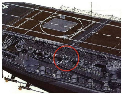
Figure 20: Kaga’s starboard 25mm gallery. Mount S#9, with landing light array, is circled. (Scanned from Gakken Pacific War Series, Volume #13.)
Positive Identification
As a result of this analysis, we strongly believe that the wreckage discovered is Kaga’s starboard #8 and #9 mounts. This area of Kaga meets all six criteria in the test case:
Both Akagi and Sôryû conclusively fail in one or more of the six criteria laid out above. A failure in any one of these areas would directly contravene the primary photographic evidence displayed by the wreckage. Only one area aboard Kaga meets all six criteria, and this location is strongly supported in the photographic record with regards to the existence of the critical landing light array. As a result, we are extremely confident (95%+) in saying that Nauticos has located mounts S#8 and S#9 of Kaga.
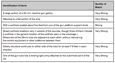
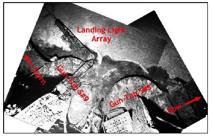
Figure 21 illustrates the gun tub numbers and their disposition aboard the ship (remember, the object is inverted.)
Figure 21: Annotated diagram of wreckage with identified tub numbers and ship orientation.
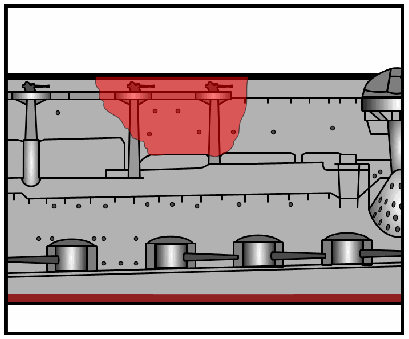
Figure 22 illustrates the approximate size and orientation of the wreckage aboard Kaga.
Figure 22: Origin of wreckage from Kaga. (Illustration by Parshall)
Analysis Part Two: Creation of the Artifact
Having identified the portion of Kaga from which the wreckage originated, the question becomes how and when was the wreckage artifact created. The appearance of the wreckage tends to support the conclusion that it was created in a violent fashion, i.e. either by being blown off the side of a carrier while the ship was in its death throes, or by being detached during the sinking of the ship as the vessel disintegrated in the water column due to hydrodynamic forces. Indeed, given the size of the object (which comprises what used to be some 55 linear feet of the ship’s side), it is difficult to conceive of a set of circumstances wherein an object of this size could be blown off, and the ship not being in a near-sinking condition. Nevertheless, given that Kaga’s main wreck was not found in the immediate vicinity of the wreckage, the supposition is that the artifact was created while the ship was still on the surface. We now turn to a discussion of the possible circumstances surrounding the creation of the wreckage.
Circumstances of the Attack
The general events of the dive-bomber attack on the Japanese Carrier Strike Force (Kido Butai) are well known. Only details pertinent to Kaga’s damage are reproduced here. At the time of the fatal attack (which began at 1020), Kaga was preparing to launch a second strike of aircraft. She and Akagi (comprising Carrier Division 1) had contributed the Type 99 (Val) dive-bomber component of the initial strike against Midway. As planned, their second strike was to comprise Type 97 (Kate) attack (i.e. torpedo) bomber aircraft and a contingent of Zero fighters. Thus, between 30-33 aircraft probably crowded her flight deck during the attack.[1]
The aircraft from her first strike had been stowed below. It can be surmised (though not proven) that her Type 99 aircraft and first-wave fighters were concentrated mainly in the forward hanger spaces (both upper and lower), since they would have been struck below via the forward elevators. Since time was of the essence in preparing the second strike, it is likely that the first wave aircraft were moved the minimum distance from these elevators in order to concentrate available deck hand labor on the more important task of bringing the second wave up to the flight deck and spotting it for launch. As is well known, ordnance was strewn about the hanger spaces, and fuel lines were in use.
Kaga was attacked by more than 20 American SBD dive-bombers beginning at 1020. During this attack she was hit at least four times. The first hit (the fourth bomb dropped) was located starboard aft, near the vicinity of the aft elevator. The second and third hits (bombs #7 and #8) struck near the forward elevator. The second hit apparently penetrated to the forward hanger spaces and detonated there, destroying the re-armed Type 99 aircraft there[2]. The third hit apparently either directly hit (or, as this author believes, caused fragments to hit) a fuel bowser parked in front of the island[3]. The detonation of the bomb and gasoline truck blew out the bridge windows and sprayed burning gasoline across the front of the island, killing everyone on the bridge, including Captain Okada. The fourth and final recorded hit (bomb #9) struck Kaga amidships to port. It should be noted that it is possible that Kaga received additional direct hits from American bombs that are not recorded. By the time of the fourth hit, Kaga’s flight deck was already burning strongly, and additional hits might not have been noticed in the confusion.
The results of this attack were devastating. Power was apparently lost very shortly after the initial bomb hit. The planes topside were soon burning fiercely. Worse yet, the hanger spaces both fore and aft were wrecked by fire and internal explosions. Commander Amagai (Kaga’s Air Officer, who had taken command of the ship after the death of Capt. Okada) was faced with an insoluble damage control problem that would worsen progressively until he ordered the ship abandoned at 1640. She suffered two large-scale detonations at 1920 (apparently as the fires finally reached the lower magazines and avgas storage spaces), and sank at 1925.
Creation of the Wreckage
The nature of the damage to the aft hanger spaces is the critical issue, since this space was adjacent to mounts S#8 and S#9. It is interesting to note that the initial bomb hit landed within 20 feet of S#9. However, it is unlikely that the detonation of a single bomb in this area would have caused the separation of such a large piece of wreckage from the ship. More likely, the wreckage was created by a combination of two factors: 1) heavy, sustained fires which weakened the ship’s structure, and 2) a powerful explosion or explosions, causing part of the gallery structure to be detached wholesale from Kaga.
As was pointed out in the Preliminary Analysis, Japanese carriers were particularly vulnerable to explosive forces in their hanger decks. Unlike British fleet carriers (which carried a heavy armor deck over their enclosed hanger spaces) and American carriers (which had unarmored flight decks, but whose hangers were lightly screened on the sides, allowing easy ventilation), Japanese carrier hangers were fully enclosed by storage spaces and other hull structure, and were also unarmored above. The result was that when a bomb did hit the hanger, explosive overpressures had nowhere to vent themselves, often leading to catastrophic damage to the ship’s structure. This effect was also true for induced explosions caused by shipboard gasoline and ordnance.
It seems somewhat unbelievable that a chunk of wreckage as large and heavy as that found on the seabed could be blown from Kaga’s starboard side without anybody noticing. On the other hand, the location of S#8 and S#9 were very near the initial point of damage, meaning that the men in the spaces nearby would have been killed or forced to flee almost immediately. It would be difficult to see this area of the ship from the bow, and survivors in the forward region of the ship might have noticed nothing more than another heavy explosion, and perhaps a large splash. They might simply have assumed that a plane had been blown overboard. It is probable that the only personnel in a position to witness the event would have been in the water nearby. Any men unfortunate enough to be in the area when such an event occurred stood chance of being killed by the wreckage falling atop them. It is notable, too, that most of the survivor’s accounts from Kaga tend to come from men who were well forward in the ship. These two reasons help explain the apparently incredible absence of any direct mention of Kaga losing two anti-aircraft mounts and a hundred or so tons of her superstructure over the side!
Timing
At some point in time, structural damage aboard Kaga’s upper hanger deck had advanced to the point where the ship began to literally fall apart. How soon, and where, this began to occur is largely a matter of guesswork. Commander Amagai’s testimony (as cited in Prange[4]) notes that “the heavy concussions [from exploding bombs and torpedoes in the hanger] blew men and even ship’s plates overboard like matchwood [my emphasis].” Unfortunately, Prange’s style of writing is sometimes less precise with temporal events than is desirable, and the timeframe of this event is difficult to know, beyond the fact that such events were occurring before the ship was abandoned at 1640. The position of this passage in Prange’s account suggests that these events were transpiring after U.S.S. Nautilus’ attack at 1359, but this is not certain.
Walter Lord’s account is similar. In it, he cites Commander Amagai being forced by the flames to retreat to the lower boat deck.[5] “Huge explosions were ripping through the side of the ship, hurling men and chunks of planes like projectiles. Amagai couldn’t reach the hanger deck, where the fire was worst, but it looked like an inferno.”[6] Again, the timing of these events is uncertain. Surely Amagai must have been forced to abandon the island fairly soon after the 1020 attack, and Nautilus would not attack for another three and a half hours, indicating that heavy explosions were already present before the submarine attacked.
On the other hand, Lord also cites the plight of Kaga’s assistant damage control officer, Lieutenant Commander Yoshio Kunisada, “…it had been a losing fight against the fires all morning. For a while [Kunisada] felt he was making some progress on the hanger deck; but then the paint began to burn, spreading a thick oily smoke that nearly suffocated his men. He had the portholes opened, but that was no answer. The draft only fanned the flames. The ports were slammed shut again, but soon Kunisda was back where he started—his men in more danger than ever. There was nothing to do but leave. The exits were all blocked, so once again the portholes were opened, and about seven of his men, including Kunisada, squeezed through. They found themselves on a narrow bulge[7] that ran along the side of the ship…” [8] It was from this precarious position that Kunisada would shortly witness the torpedo attack of the Nautilus. The timing and nature of Kunisada’s account would seem to indicate that Kaga’s hanger deck was only beginning to slide towards violent self-destruction by about the time the American sub attacked. Up until shortly before the attack Kunisada was still battling the fire with some limited degree of optimism. This surely would not have been the case if Kaga were already self-destructing to the degree necessary to create the wreckage artifact.
In the opinion of this analyst, the nature of the damage control efforts aboard Kaga seem to indicate a gradual loss of the battle, rather than an outright rout. The men aboard Kaga fought her fires for more than eight hours. On Sôryû, by contrast, the ship was abandoned within twenty-five minutes of being bombed. The fact that Kaga’s men battled for as long as they did indicates that 1) the men must have felt that there was some remote hope of saving the ship, and 2) the bomb and avgas storage spaces were not being directly affected by the fires, which would have destroyed the ship outright. If those vital spaces had been directly threatened, Kaga would likely have been abandoned in the same fashion as Sôryû, which was abandoned shortly after fires reached her forward avgas storage spaces.
In summary, given the evidence at hand, it seems highly unlikely that the initial American bomb hit caused the creation of the wreckage artifact (such a powerful initial hit would surely have been noted in the war log). Similarly, it seems unlikely that Kaga was falling apart instantaneously after the attack. Even in the face of the severe heat present in the aft hanger deck, it would have taken time, perhaps several hours, for the metal on the hanger deck sides to turn red hot and begin to lose their structural integrity. If Kunisada’s account is any indication, it may be that Kaga did not begin truly self-destructing until after Nautilus’ attack, in the 1400 range. At this point, the metal would have been weakened enough that a large internal explosion close by might have been able to separate the main portion of the wreckage from the remainder of the hull.
At a guess, then, the creation of the wreckage artifact probably occurred after 1400, but before the powerful twin explosions at 1920. In other words, the wreckage may be as far as five and half hours (at whatever drifting speed was prevalent) from the main wreck itself. It is unfortunate that we cannot narrow the event down any further, but the gaps in the accounts of Kaga’s survivors are very large. Only the discovery of the main wreck, and its relative position to the wreckage artifact, are likely to solve the question of when the wreckage was actually created.
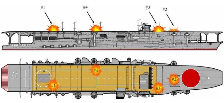
Figure 23: Known bomb hit locations on Kaga. (Illustration by Parshall)
[1] Sources vary regarding both the actual number of Type 97 aircraft carried by Kaga during the Midway operation (either 18 or 27), and the number of Type 0 fighters slated for the second strike (either 3, 4 or 6). John Lundstrom, in an email to this author, states that 27 Type 97 attack bombers is the correct figure for Kaga, but ventured no opinion as to the number of Zero fighters to be launched, given the very chaotic nature of the Japanese CAP at the time of the attack.
[2] The fuzing on the American bombs was such that they were supposed to penetrate a flight deck and detonate a short distance below it. The second hit on Kaga apparently did just that.
[3] The presence of a fully loaded fuel bowser on the flight deck of a ship that had been recently undergoing American attacks illustrates just how desperate the Japanese must have been to refuel their CAP fighters and keep them aloft during the morning’s air battles.
[4] Miracle at Midway, p. 310.
[5] This was located on the starboard side of the ship, directly below the ship’s superstructure, at approximately the level of the upper hanger deck.
[6] Incredible Victory, p. 181.
[7] This can only be the Kaga’s anti-torpedo blister, which indicates that Kunisada was fighting fires on the lower of Kaga’s two hanger decks.
[8] Ibid, p. 210.